Python meets
Hardware
Survival Guide
Carlos Pereira Atencio
#PyConES2026

- Python
- MicroPython
- CircuitPython
A bit about me

Carlos Pereira Atencio
- Embedded Software in Aerospace, Telecoms and EdTech
- Embedded Lead @ Micro:bit Educational Foundation
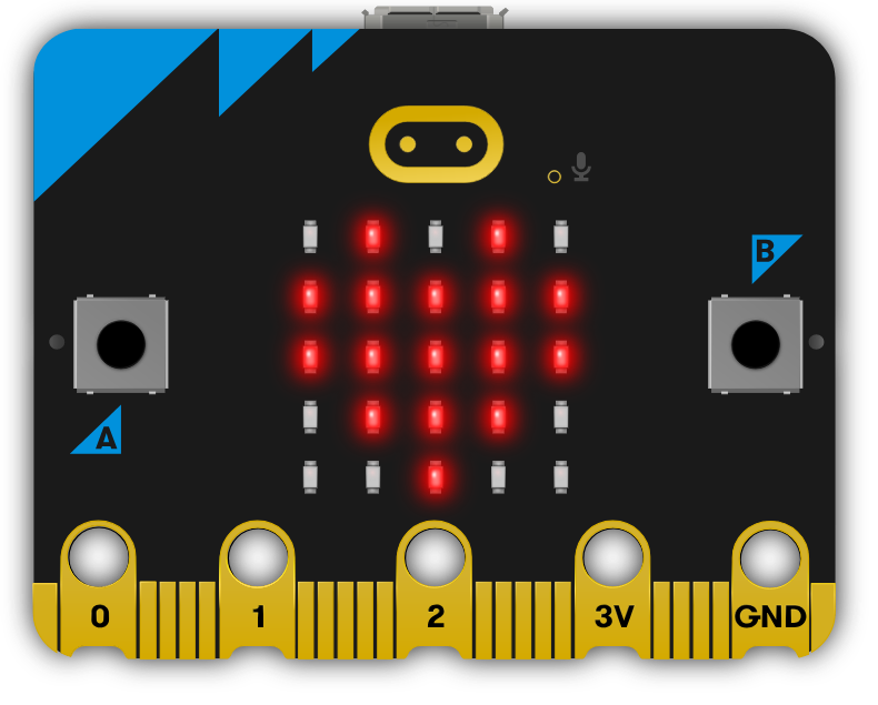
- 10 years of BBC micro:bit + MicroPython
 ❤️🐍
What to expect from this talk?
1. Blink an LED
2. Build the rest of the owl
- Device Resources
- Drivers
- Debugging
- Tooling
- AI
But there is a lot more!
Scan the QR to follow along during the talk,
or at your own pace.
https://pycones2026.embeddedlog.com
This is a vertical slide!
This is an example of slides that sit below the main track.
These contain additional content with more depth, resources, and links.
- The arrows in the corner show which ways you can go.
- Arrow down appears? press ↓, or swipe up to view additional slides.
- Back to the talk? press →, or swipe left.
MicroPython, CircuitPython, all the Pythons
MicroPython, CircuitPython, all the Pythons
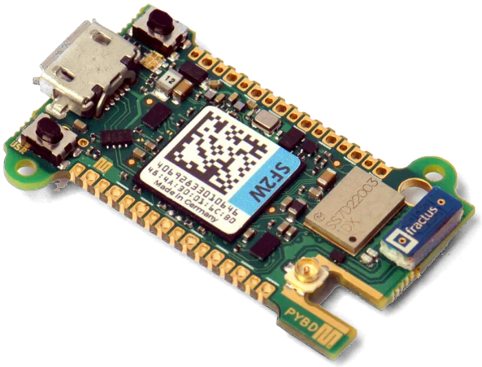
MicroPython
Pyboard D
microcontroller
  import pyb

  # On board green LED on pin 2
  led = pyb.LED(2)
  while True:
      led.toggle()
      pyb.delay(500)
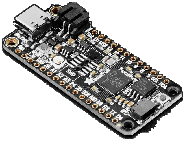
CircuitPython
Feather RP2040
microcontroller
  import time
  import board
  import digitalio

  led = digitalio.DigitalInOut(board.LED)
  led.direction = digitalio.Direction.OUTPUT
  while True:
      led.value = True
      time.sleep(0.5)
      led.value = False
      time.sleep(0.5)
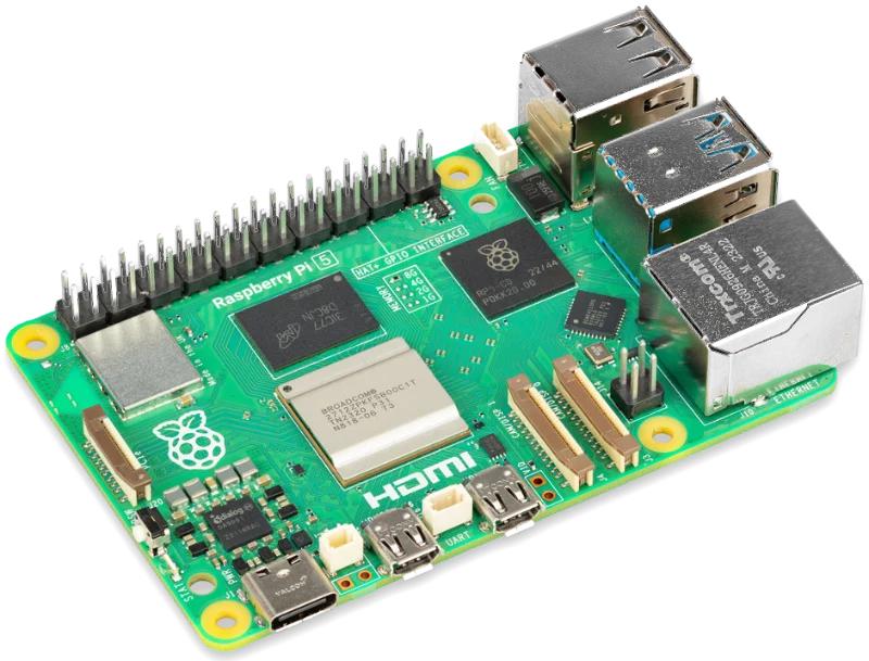
CPython + gpiozero
Raspberry Pi 5
Single Board Computer
  from time import sleep
  from gpiozero import LED

  # An LED wired to GPIO17
  led = LED(17)
  while True:
      led.toggle()
      sleep(0.5)
MicroPython and CircuitPython
MicroPython
A lean Python 3 for microcontrollers, by Damien George.
The most from each chip. machine works on
every board, and each port (the build for one chip family) adds modules for what its chip can do.
CircuitPython
Adafruit's fork of MicroPython, for beginners and education.
The same code everywhere. One API on every board; a board that can't support a module leaves it out.
Blinka brings that API and Adafruit's drivers to CPython on single-board computers like the Raspberry Pi.
Sources: MicroPython libraries · CircuitPython core modules
Where they differ
| MicroPython | CircuitPython | |
|---|---|---|
| Hardware | machine, plus a module per port | board, digitalio, busio on every board |
| Pins | The port ids: Pin(15), Pin("GP15") | The board's labels: board.D5, board.LED |
| Concurrency | Pin interrupts, timers, _thread, asyncio | No interrupts or threads; asyncio |
| Workflow | Copy files with mpremote or Thonny | A USB drive: save code.py and it reruns |
| Files | Your code reads and writes them | Read-only to code, unless boot.py remounts |
| Libraries | mip, from micropython-lib | circup, from a bundle |
Sources: CircuitPython README, FAQ, storage | MicroPython docs
What's under your code
On your computer
On a microcontroller (MCU)
machineWhat happens at power-on
| MicroPython | CircuitPython | |
|---|---|---|
1) boot.py | Runs first, and should exit | Runs once, before USB starts |
| 2) your code | main.py; it may loop forever | code.py in a fresh VM; reruns on save |
| 3) when it ends | The REPL, with main.py's variables | The REPL, in another fresh VM |
| Ctrl-D | Soft reset: boot.py, then main.py | Reload: code.py again |
Sources: MicroPython reset and boot · CircuitPython README
What's different to "normal" Python
- Memory! KBs, maybe MBs, of RAM & flash
- CPU frequencies in MHz, not GHz
- Python standard library is limited
- Same language we love, just with tighter constraints
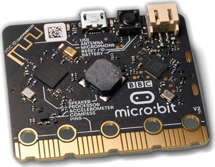 micro:bit V2128 KBFeather RP2040264 KB
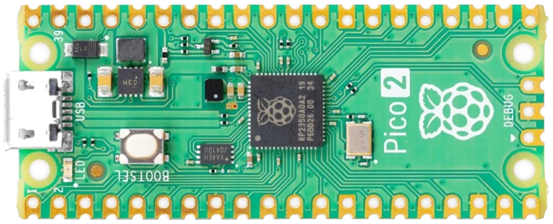 Pico 2520 KB
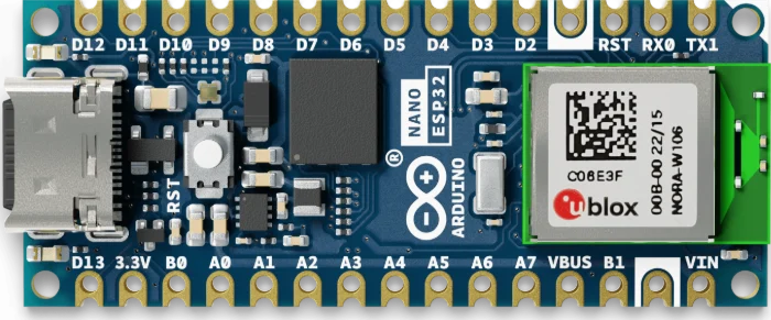 Nano ESP328 MB PSRAM
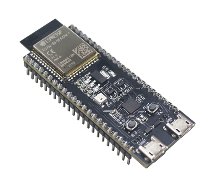
16 MB PSRAM
ESP32-S3-DevKitC-116 MB PSRAM
Something very different: Interrupts
A pin edge or a timer can pause your programme and run an interrupt.
from machine import Pin
presses = 0

def on_press(pin):  # the interrupt handler
    global presses
    presses += 1    # an int: no new object

button = Pin(BUTTON_PIN, Pin.IN, Pin.PULL_UP)
# a press pulls the pin low: a falling edge
button.irq(on_press, Pin.IRQ_FALLING)
Not on CircuitPython: use countio, keypad
- Soft Interruptdefault for pins: queued, so it can lag. May allocate
- Hard Interrupt
hard=True: runs at once, heap locked: no floats orappend() - Hard → soft
micropython.schedule(f, arg)fruns soft, soon after - Be briefyour program waits, no
print(),sleep()or filesystem actions
Read: Writing interrupt handlers | Pin.irq() | Timer | schedule()
Common ways to run out of RAM
MemoryErrorwhen an allocation didn't find enough contiguous free memory.
Large allocations
One list/array, buffer or string larger than available memory.
Importing modules
When we get tracebacks on an import line.
Fragmentation & leaks
Free memory goes down over time or gets fragmented.
import gcprovides functions to check and manage memory.
Read your own heap
>>> import micropython
>>> micropython.mem_info(1)
GC: total: 64000, used: 9824, free: 54176
 No. of 1-blocks: 112, 2-blocks: 31, max blk sz: 64, max free sz: 3317
00000000: MDhhBTT=h===DhBBhSShhLh=hF.FF.S=..hhh=....Ah=======.....S=S=....
          S str · L list · D dict · F float · h other · = rest of one object
- max free szthe largest hole: 3317 blocks × 16 = 53,072 bytes
- the mapyour heap, one character per 16-byte block;
.is free - MemoryErrorasks for < free but > max free sz: memory is in pieces
- CircuitPythonno
mem_info();gc.mem_free()gives totals.
ESP32:espidf.heap_caps_get_largest_free_block()
Which lines cost memory?
import,def,class- a new list, dict, str or bytes
s + t,f"{t}",data[4:20]uart.read(64)- float maths, even
n / 2*
if,for,while,try- locals, small-int maths:
n += 1 - calling a function or a method
- reading a pin:
pin.value() - writing into a buffer:
buf[i] = b
Control flow is free. Each new object takes at least one 16-byte block.
From Damien George, PyCon AU 2018 | *MicroPython only
Small tweaks to common habits
packet[4:20] | → | a memoryview does not copy data |
uart.read(64) | → | uart.readinto(buf) reuses one buffer |
| magic numbers as globals | → | const() |
| 1,000 floats in a list | → | array("f"): ~4 KB, not ~20 KB |
header = packet[4:20]     # ✕ From a bytearray, copies data
mv = memoryview(packet)   # ✓ create memoryview
header = mv[4:20]         # ✓ view into packet, no copy
data = uart.read(64)      # ✕ new bytes object each time
buf = bytearray(64)       # ✓ create once
n = uart.readinto(buf)    # ✓ reuse when reading data
REG_ID = 0xD0           # ✕ a global, looked up by name
from micropython import const
_REG_ID = const(0xD0)   # ✓ in the bytecode, no global
temps.append(sensor.temperature)  # ✕ ~20 KB of floats
temps = array("f", [0] * 1000)    # ✓ raw floats: ~4 KB
temps[i] = sensor.temperature
Keeping memory under control
Falling over hours? Something grows: a leak.
gc.collect()
print(gc.mem_free())  # once a minute
Not when an allocation fails mid-task.
while True:
    read_sensor()
    gc.collect()  # the quiet point
While locked, any allocation raises an error.
# MicroPython only
micropython.heap_lock()
handle(packet)  # allocates? MemoryError
micropython.heap_unlock()
Log the error, then reset to an empty heap.
try:
    app.run()
except MemoryError as e:
    log_crash(e)     # to crash.log
    machine.reset()  # a fresh heap
Read: MicroPython gc · heap_lock() · MicroPython on microcontrollers
Your code lives in RAM too
import bme280 # a 10 KB .py driver
Parse: the whole file becomes a tree of nodes, in RAM.
Compile: the tree becomes bytecode, while the tree is still there.
Then the tree is freed. The bytecode stays.
The import fails on the peak, not on what stays.
.mpy: file compiled on your machine via mpy-cross. The bytecode still loads into RAM.
ROMFS: bytecode saved into a special filesystem in flash.
Frozen: bytecode compiled into the MicroPython build.
Where your .mpy lives
A .mpy is a .py already compiled by mpy-cross on your computer. Different locations provide different trade-offs.
| Where | ✓ Good | ✕ Watch out | RAM* |
|---|---|---|---|
Filesystemmpremote cp |
Any firmware; update in seconds | Bytecode and names load into RAM. Needs a matching mpy-cross |
6.3 KB |
ROMFS v1.25+mpremote romfs |
Runs from flash; no firmware rebuild | Needs a ROMFS partition: few firmware builds have one | 4.1 KB |
Frozenmanifest.py |
Least RAM; no filesystem needed | Rebuild and reflash the firmware for every change | 1.2 KB |
*RAM after importing a 10 KB driver, unix port.
Memory fragmentation
readings = []
for _ in range(9):
    readings.append(read())        # kept: a float, 1 block
    msg = "T=%.1f" % readings[-1]  # dropped next time: a str, 2 blocks
big_array = bytearray(64)          # 64 bytes: 4 blocks in a row
big_array = bytearray(64)          # first, while the heap is empty
readings = []
for _ in range(9):
    readings.append(read())
    msg = "T=%.1f" % readings[-1]
1 square = 1 block = 16 bytes
FS=FS=FS=FS=FS=FS=FS=FS=FS=
F..F..F..F..F..F..F..F..FS=
A===FS=FF.FS=F..F..F..FS=F.
The loop fills the heap: each float kept, each string dropped
No room for big_array, so the collector frees the strings:
We have 256 B free, but the biggest hole is 2 blocks = 32 B
✓ the loop fills and frees the space after it; big_array keeps its room
A===
✕ MemoryError: memory allocation failed, allocating 64 bytes
Allocate big buffers early, right after your imports.
And reuse them!
Leaks: bound what grows
readings = []
while True:
    readings.append(read())  # ✕ forever
from collections import deque
readings = deque((), 6)      # ✓ the last 6
while True:
    readings.append(read())
1 square = 1 reading · gold: the newest
FFFFFFFFFFFFFFFFFFFFFFFFFFF
the list keeps growing ✕ MemoryError
FFFFFF.....................
✓ the deque: newest replaces oldest
- Whythe collector can't free what the list still points to
- Spot itif no other allocations happening and
gc.collect()+gc.mem_free()shows less free mem over time. - Also growsa log string, a cache
dict, callbacks added on every reconnect - No deque?use an
arrayas a ring buffer
Read: MicroPython collections.deque · MicroPython on microcontrollers
Fewer cycles, so make them count
def checksum(buf):
    s = 0
    for b in buf:
        s += b
    return s & 0xFFFF
@micropython.native
def checksum(buf):
    s = 0
    for b in buf:
        s += b
    return s & 0xFFFF
@micropython.viper
def checksum(buf) -> int:
    p = ptr8(buf)
    s = 0
    for i in range(int(len(buf))):
        s += p[i]
    return s & 0xFFFF
Measurements from Adafruit
- nativeyour Python compiled to machine code, not bytecode
- viperraw ints and pointers: no floats, no overflow checks
- Turbonative & viper for CircuitPython, built on a computer
Small tweaks for speed
Time it first, then change only the slow part.
| code at module level | → | inside a function (def main():) code in global space is slow |
| a method call in a hot loop | → | toggle = led.toggle save it locally, before the loop |
| a Python loop over a buffer | → | Use built-in functions like sum(buf), more efficient |
| float maths in a fast loop | → | Use integers with a larger scale (int millivolts instead of float volts) |
| parsing sensor bytes by hand | → | struct.unpack_from("<hhh", buf): one call, signs right |
Read: Maximising MicroPython speed · Damien George's 2018 talk slides
Time every call with a decorator
Put @timed above a function, and each call prints how long it took.
import gc, time

def timed(f):
    name = str(f).split()[1]  # portable name
    def wrapper(*args, **kwargs):
        gc.collect()  # no GC mid-timing
        t0 = time.ticks_us()
        result = f(*args, **kwargs)
        dt = time.ticks_diff(time.ticks_us(), t0)
        print(name, dt, "us")
        return result
    return wrapper
- Time a few calls: the first is often slower.
- Ticks wrap: use
ticks_diff(). - Not for async: on
async defit only times creating the coroutine. - CircuitPython: use
time.monotonic_ns().
Your Python controlling the real world

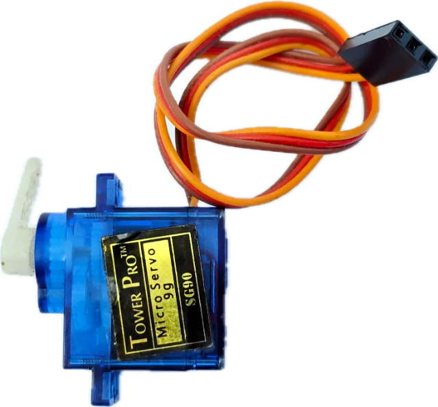
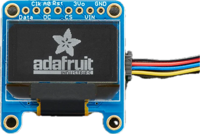
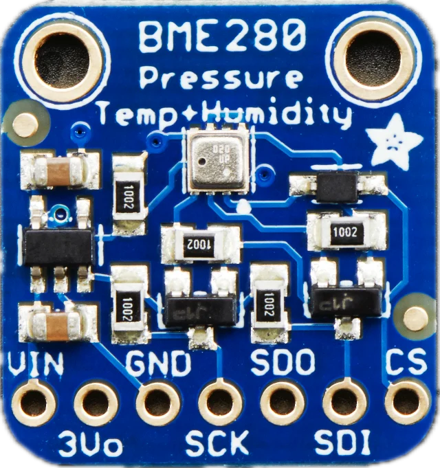
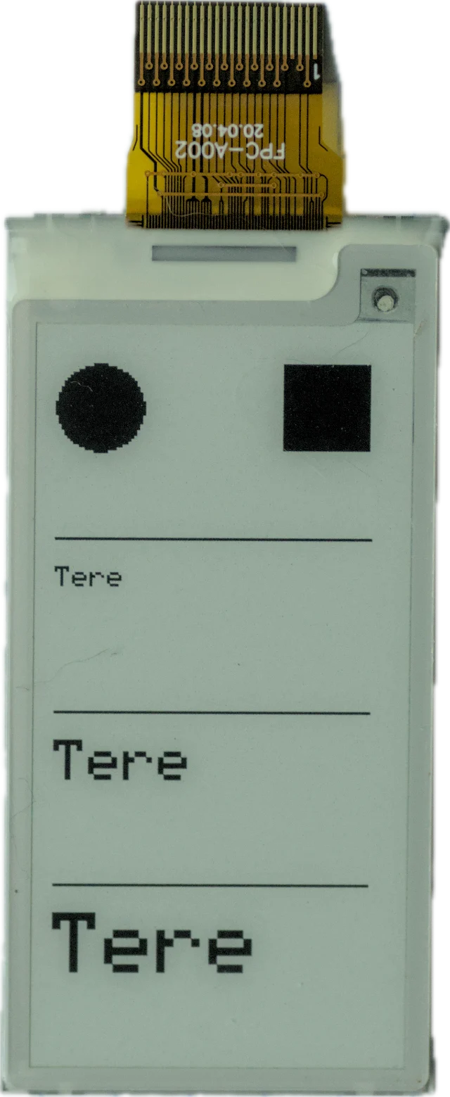
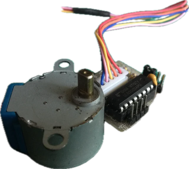
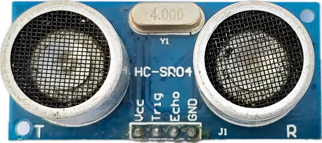
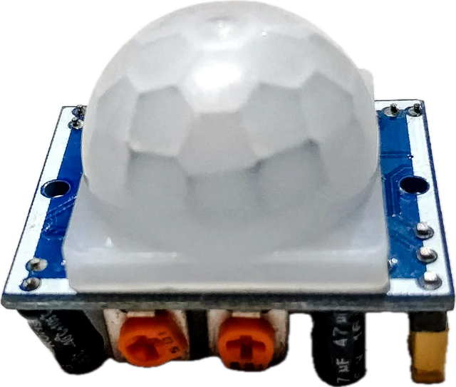
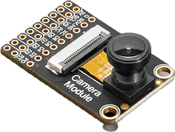
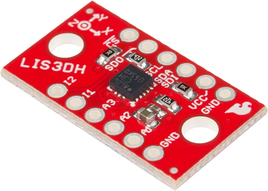
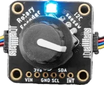
Different parts might use different signals, protocols, and timings.A driver abstracts that to provide their functionality.
First step: find an existing driver
- Read the official docs. Vendors might provide all you need.
- Find the chip name. Board name might not be the same as the chip (e.g.
BME280). - Start with Google, but also use GitHub's search with filters.
- Check micropython-lib, awesome-micropython, awesome-circuitpython, vendor's repos (Adafruit, SparkFun, Pimoroni, Arduino).
- Check it's for your Python.
E.g.machine.I2Cis MicroPython;busiois CircuitPython. - Only in C or Arduino? Port it, it's a great reference implementation.
Getting the driver onto your board
MicroPython
$ pip install mpremote
$ mpremote mip install \
    github:robert-hh/BME280
import bme280_float as bme280
bme = bme280.BME280(i2c=i2c)
By hand: mpremote cp bme280_float.py :
CircuitPython
$ pip install circup
$ circup install adafruit_bme280
from adafruit_bme280 import basic as bme280
bme = bme280.Adafruit_BME280_I2C(i2c)
By hand: drag the .mpy into CIRCUITPY/lib
No driver? You can write it in Python!
from machine import I2C
from bme280 import BME280

sensor = BME280(I2C(0))
print(sensor.temperature)
Your code asks for the temperature; the driver handles the details.
class BME280:
    def __init__(self, i2c, addr=0x76):
        chip_id = i2c.readfrom_mem(addr, 0xD0, 1)
        if chip_id != b"\x60":
            raise OSError("BME280 not found")
The driver: Python code that sets up and reads the sensor.
MicroPython, written in C, gives your Python an API for the microcontroller.
The chip maker's C library: low-level access to the microcontroller.
One level down: registers
A register is a memory address wired to the hardware.
Write a bit there, and a pin changes.
from machine import Pin, mem32

led = Pin(25, Pin.OUT)  # MicroPython sets the pin up

# RP2040 addresses, from its datasheet
GPIO_OUT_SET = 0xD0000014
GPIO_OUT_CLR = 0xD0000018

mem32[GPIO_OUT_SET] = 1 << 25  # bit 25: "set" LED on
mem32[GPIO_OUT_CLR] = 1 << 25  # "clear" LED off
- The microcontroller datasheets explains all registers.
- Each chip has its own register memory map: on an RP2350,
GPIO_OUT_SETis at0xD0000018. - This is what drivers and SDKs do. Use
mem32only when needed.
A driver is a small class
from micropython import const
_ID = const(0xD0)
_CTRL = const(0xF4)
_TEMP = const(0xFA)

class BME280:
    def __init__(self, i2c, addr=0x76):
        self.i2c, self.addr = i2c, addr
        self._buf = bytearray(3)
        if i2c.readfrom_mem(addr, _ID, 1) != b"\x60":
            raise OSError("BME280 not found")
        i2c.writeto_mem(addr, _CTRL, b"\x27")  # wake

    def raw_temperature(self):
        b = self._buf
        self.i2c.readfrom_mem_into(self.addr, _TEMP, b)
        return b[0] << 12 | b[1] << 4 | b[2] >> 4
- Registers as
const() - Take the bus, don't make it:
I2C,SoftI2Cor a fake one for tests - Check the ID, wake it up
- One buffer, reused
Which communication bus?
- A bus is a set of signals between chips & rules for exchanging data (the protocol).
- Microcontrollers have built-in hardware for common ones like: UART, I²C and SPI.
- You rarely choose: the part's datasheet or product page specifies the bus.
- You still need to know it: it decides which pins you wire, and what bus you hand the driver.
i2c = I2C(0, scl=Pin(5), sda=Pin(4))
bme = bme280.BME280(i2c=i2c)
- Not every part needs a bus: buttons use a plain pin (GPIO), servos use pulses (PWM), analogue sensors a voltage (ADC).
- Some buses might not be built into the microcontroller, but can be implemented in software.
UART: no clock, so agree in advance
UART sends bytes one bit at a time from TX to the other end's RX. There is no clock wire, so both ends agree on the speed, the baud rate, in advance.
'A' = 0x41 = 0100 0001 · sent least significant bit (LSB) first
Idle: the line sits HIGH while nothing is sent.
START: the line drops for one bit. The receiver starts timing from this edge.
Eight data bits, least significant first: 'A' goes out backwards.
STOP: back to HIGH for at least one bit, ready for the next byte.
The receiver samples the middle of each bit at its baud rate. Send at 9600, read at 19200: garbage, and no exception.
SPI: to read, you must write
SPI has a clock, a wire each way and a chip-select (CS) per device. Every tick moves one bit each way.
cs(0); spi.write_readinto(b'\xD0\x00', buf); cs(1) → buf[1] == 0x60
Idle: CS is HIGH, so the sensor ignores the bus.
cs(0): CS goes LOW and selects the BME280.
Byte 1: the microcontroller sends 0xD0, the ID register (bit 7 = read). The reply is ignored.
Byte 2: the microcontroller sends a dummy 0x00. Its 8 clocks shift 0x60 back on CIPO.
cs(1): done. No ACK, so no scan(): reading a known ID register is SPI's scan().
COPI/CIPO: MOSI/MISO on many boards · machine.SPI · BME280 datasheet
I²C: reading the chip ID, bit by bit
SCL is the clock, SDA the data, both shared. The microcontroller (MCU) reads the chip ID:
i2c.readfrom_mem(0x76, 0xD0, 1) → b'\x60'
S start · W write · R read · A✓ ACK · Sr repeated start · N NACK · P stop
New sensor ready to go, but...
...but nothing happens, not even an error. Could it be the...
- Code? the wrong pins, the wrong config, the wrong constructor?
- Driver? the wrong defaults, similar but different chip, incomplete implementation?
- Wiring? signals swapped, a loose jumper, a bad breadboard or solder joint?
- Power? no power to the sensor, wrong voltage, grounds aren't joined?
- Part? is it dead, a different version, or a known chip bug (errata)?
Where do we start?
Stop guessing, start debugging
- Look first: Disconnect power, inspect for damage, heat, a burnt smell? Check cables
- Check power: Measuring voltage & ground, check signal directions and pins.
- Make it fail: the smallest test that consistently reproduces the issue.
- Change one thing at a time: and write down what you changed.

"Remember kids, the only difference between screwing around and science is writing it down." Adam Savage, MythBusters
- Get a fresh view: explain it, or ask online/ai. Include code, wiring & the error.
Nine rules for debugging
- Understand the system
- Make it fail
- Quit thinking and look
- Divide and conquer
- Change one thing at a time
- Keep an audit trail
- Check the plug
- Get a fresh view
- If you didn't fix it, it ain't fixed
David J. Agans, Debugging: The 9 Indispensable Rules for Finding Even the Most Elusive Software and Hardware Problems · Embedded Artistry summary · Interrupt: debugging ill-defined problems
Check power & cables
- Cables: Some USB cable only charge. Use a known‑good data cable.
- Battery banks: Some switch off when the board draws too little current.
- Voltage: Ensure the right voltage level is used for your device and any components.
- Ground: Has to be shared by every board and supply. Breadboard rails can be split.
- Under load: Resets when a motor or Wi-Fi starts? A brownout. A meter misses it.
Wiring: look, wiggle, slow down, swap
Fine sometimes, and flaky others? Maybe something moved.
A good solder joint is smooth and concave. Lumpy or grainy may not connect at all. Headers must be soldered, not just pushed in.
Press on wires and parts as it runs. Comes and goes as you move? A connection. Changes with just a hand nearby? A floating input: add Pin.PULL_UP/DOWN.
Lower the bus speed, I2C(0, freq=100000), or the baud rate. Works now? Suspect the wires or pull-ups, not your code.
Another wire, another sensor, another board. A part you know works tells you which half is broken.
Most of your debugging habits still work
Tracebacks, print() | Stdout is serial via USB cable: keep a terminal open |
logging | With filesystem access you can log into a file |
| REPL | An interactive shell can poke the live hardware |
| Time/profile | time it on the chip, or on a spare pin |
unittest | run it on-device, or use micropython-mock-machine on PC |
Traceback (most recent call last):
  File "main.py", line 14, in <module>
OSError: [Errno 5] EIO
>>>
except Exception as e:
    log.exception("failed", exc_info=e)  # or no traceback
    handler.stream.flush()               # or lost on a reset
>>> i2c.scan()        # ask the live bus
[118]
>>> led.value(1)      # and the LED lights up
t0 = time.ticks_us()
read_sensor()
print(time.ticks_diff(time.ticks_us(), t0), "µs")
$ mpremote mip install unittest
$ mpremote mount . run test_readings.py
test_in_range (TestBME280) ... ok
OK
Make time visible
No debugger on the board? Time your code with a spare pin, or measure with ticks.
dbg = Pin(DEBUG_PIN, Pin.OUT)   # any free pin
dbg.on(); read_sensor(); dbg.off()
t0 = time.ticks_us(); read_sensor()
print(time.ticks_diff(time.ticks_us(), t0))
Logic analyser: your pin is high while your code runs, once per interrupt.
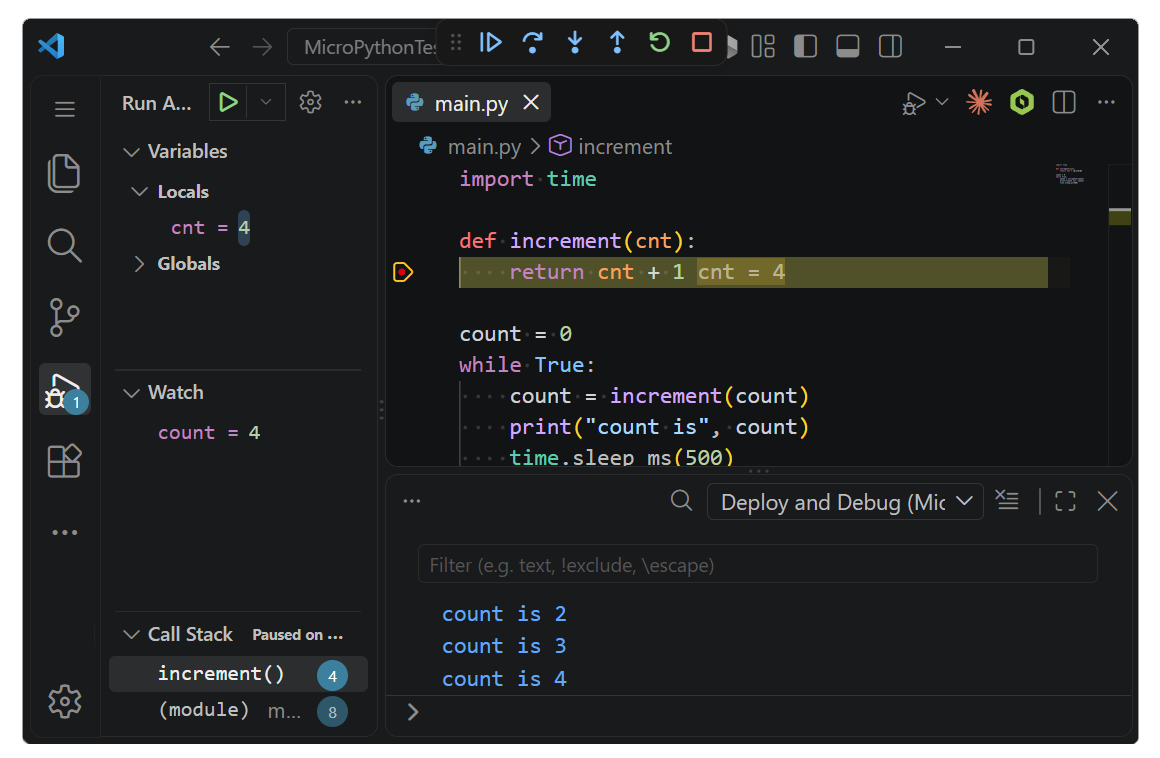
Breakpoints on the board
GHI Electronics has recently released a MicroPython Debugger.
Breakpoints, stepping, variables and watch in the Python code.
Via USB cable, no debug probe needed.
Runs as a VS Code extension.
Developed as a MicroPython fork.
Only runs on Pico, Pico 2 and ESP32 boards so far.
Getting down to the wire: which tool?
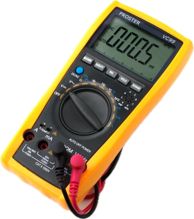
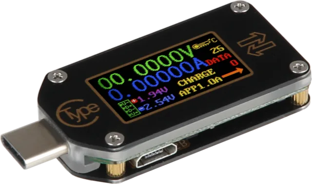
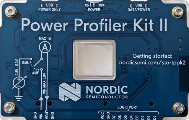
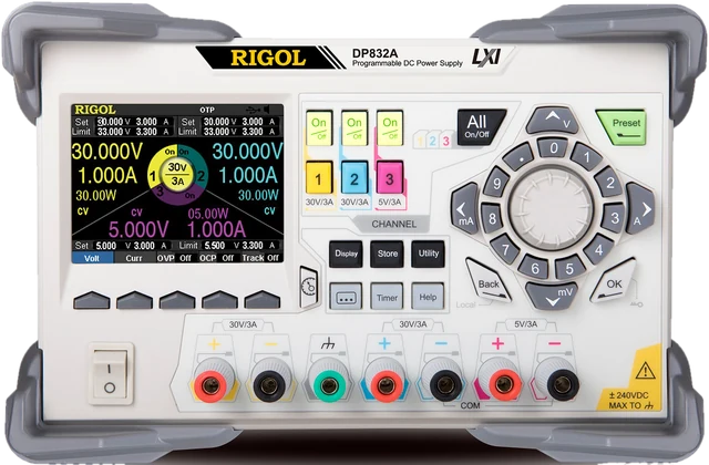
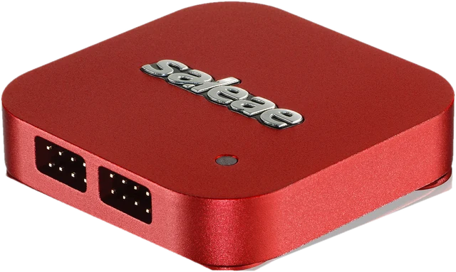
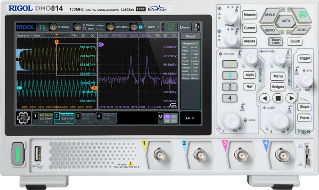
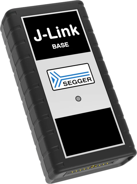
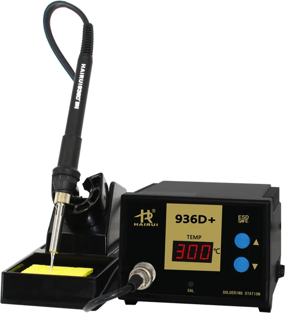
Tools can be expensive, but we'll focus on good value options.
What each tool sees
| Voltage | Volts over time | Bits & protocols | Current | CPU state | |
|---|---|---|---|---|---|
| Multimeter | ✓ | ✓ | |||
| USB power meter | ✓ | ✓ | |||
| Oscilloscope | ✓ | ✓ | |||
| Logic analyser | ✓ | ||||
| Power profiler | ✓ | ||||
| Debug probe | ✓ |
Debug probe
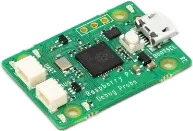
- Gives you a serial console on the board's UART pins, and SWD: the chip's own debug port.
- Use it for: flashing or rescuing a board without its boot button, and logs when USB is busy.
Raspberry Pi Debug Probe: cables and a case included. For the Pico and other Arm boards at 3.3 V.
The probe and your Python
- A console: bridges UART from the board to a different USB port. MicroPython can copy its REPL there.
- Flashing: SWD writes new firmware with no button to press.
- Debugging means the C firmware running the Python code, not your
.py.
- Raspberry Pi: Debug Probe documentationDocs: wiring, flashing, console
- MicroPython rp2 quick reference: UARTDocs: the REPL on a UART
- Kevin McAleer: the Raspberry Pi Debug ProbeVideo, 5 min
You may already have a probe
- A spare Pico: flash Raspberry Pi's debugprobe firmware and it works as a Debug Probe, for about €4.
- ESP32-S3, C3 or C6: USB-JTAG is built into the chip. One USB cable, then OpenOCD.
- BBC micro:bit: its second chip is a probe and a serial port, called DAPLink.
- raspberrypi/debugprobeGitHub: firmware for a Pico or Pico 2
- Espressif: built-in JTAGDocs: the ESP32-S3 page
- micro:bit: the DAPLink interfaceDocs
Other low-cost probes
| Probe | About | For | Worth knowing |
|---|---|---|---|
| Black Magic Probe | €66 | Arm chips | GDB server built in: no OpenOCD |
| ESP-Prog | €17 | Original ESP32 | Espressif's own: JTAG, flashing and serial |
| J‑Link EDU Mini | $76 | Most Arm chips | Education version of SEGGER's professional J‑Link: non-commercial only |
| NXP MCU-Link | €17 | Arm chips | CMSIS-DAP, as DAPLink probes speak |
| DAP Cat | $5 | Arm chips | Open source CMSIS-DAP, with serial |
Not every probe can debug a Pico's chip: check it supports the RP2040 or RP2350.
A probe needs OpenOCD or pyOCD
- The probe only moves bits between USB and the chip's debug port.
- The tool knows your chip: its memory, its cores, and a small program it loads into RAM to write the flash.
- It serves GDB and VS Code: breakpoints, single steps, registers.
The exception: a Black Magic Probe runs the GDB server on the probe itself.
USB-UART adapters: about €5
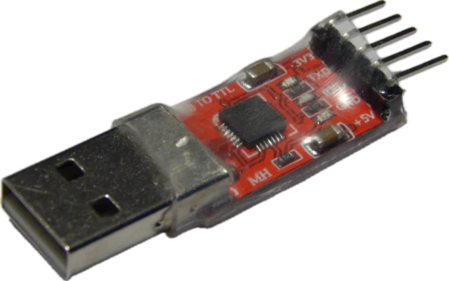
- Set it to 3.3 V: 5 V can damage a 3.3 V board.
- Cross the wires: TX to RX, RX to TX, and GND to GND.
- Often built in: most ESP32 boards and the micro:bit have one. Some, like the ESP32-CAM, don't.
- SparkFun: Serial CommunicationDocs: see "Common Pitfalls"
- SparkFun: Logic LevelsDocs: why 3.3 V
- Rohde & Schwarz: Understanding UARTVideo, 6 min
- SparkFun: installing CH340 driversWritten
Multimeter
- Shows volts, ohms and amps, and a beep when two points connect.
- Use it for: checking power, a wire that isn't connected, a short.
Aneng AN8008 or similar: auto-ranging, with a continuity beep. For low-voltage electronics, not mains.
USB power meter
- Shows the volts and amps going into your board over USB, as it runs.
- Use it for: resets when a motor starts, flat batteries, your power budget and calculate battery life.
RD TC66C or any meter that reads to 0.1 mA. It plugs in between the computer and the cable.
What a USB meter misses
- Short spikes: it reads a few times a second, so a spike can fall between readings.
- Sleep current: microamps, too small for most USB meters. That's a power profiler's job, such as Nordic's PPK2.
- On USB, CircuitPython only pretends to sleep. Measure deep sleep on a battery.
- Adafruit: Deep Sleep with CircuitPython, powerWritten, with PPK2 graphs
- Andreas Spiess: measuring low currentsVideo, 18 min
- HKJ: RD Tech TC66C, testedWritten, against lab meters
- Nordic: Power Profiler Kit IIProduct page and specs
When you need a power profiler
- Shows current as a graph, 100,000 readings a second: microamps (µA) asleep, milliamps (mA) when running.
- Provides power can also be used as a power source for testing.
- Use it for: battery life. Toggle a pin from Python to mark your code on the graph.
- Nordic's Power Profiler Kit II (PPK2), I generally recommend this product, only downside is price ~€100.
- Adafruit: Wi-Fi Mailbox Notifier, powerWritten: CircuitPython, the PPK2 as its battery
- Nordic: PPK2 user guideDocs: both modes, wiring, the app
- IRNAS/ppk2-api-pythonGitHub: read it from Python, unofficial
Logic analyser: a real view into the signals
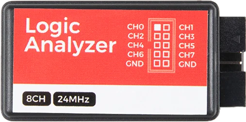
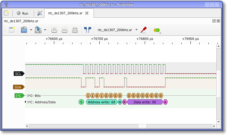
- Shows the 0s and 1s on the bus signals, decodes the data of I²C, UART, SPI, and more.
- Use it for: did the sensor answer? What did your code send?
Search for a 24 MHz 8-channel USB analyser in AliExpress or Amazon.
Use it the open source app PulseView.
What you'll see
A good read: chip ID 60
Wrong address: no answer
OSError: [Errno 5] EIO · Python says that. The wire says why.
D0, D1: channels · S start · Sr restart · A ACK · N NACK · P stop · hex
Logic analyser: getting started
- GND first, then a channel per signal: SDA, SCL.
- Sample at least 4× faster than the signal: 24 MHz is plenty for I²C and UART.
- Add a decoder for I²C, UART or SPI. PulseView's are written in Python.
- A bare Pico is 3.3 V only; the €10 analyser copes with 5 V too.
- SparkFun: USB Logic Analyzer with PulseViewDocs: install to decoded UART
- sigrok: Getting started with a logic analyzerDocs: decode a sample, no hardware
- gusmanb/logicanalyzerGitHub: a Pico as a 24-channel analyser
- element14: Instrument Basics, Logic AnalyzerVideo, 12 min
When you need an oscilloscope
- An analyser sees 0s and 1s. A scope sees the shape of the voltage: a sagging supply, slow I²C edges, PWM.
- Not a first buy. Later: a FNIRSI 2C53T handheld, about €85, or a Rigol DHO802 bench scope, about €390.
- SparkFun: How to Use an OscilloscopeWritten, with "When to use one"
- Rohde & Schwarz: How to use an oscilloscopeVideo, 8 min
- Tektronix: XYZs of OscilloscopesFree PDF primer
- GreatScott!: buying and using a scopeVideo, 13 min
Your agent is new to hardware too
“Claude forgets that my ESP32 isn’t a full computer” Nick Lewis, How-To Geek, September 2026
- But it is rapidly learning
- It still reaches for CPython modules, and makes bad assumptions
- But with enough guidance, it does significantly better

What the benchmarks measured
EmbedBench: 126 small tasks on Arduino, ESP32 and a Pico running MicroPython. It tested 2025 models; around last December/January.
- Typical misses: voltage logic, debouncing and wrong APIs.
- Second benchmark, PCEval, adds breadboard layout and pins.
Help your agent
- A good
AGENTS.mdcontains info about the hardware and reference code/projects. - Give it skills
- Tell it how to interact with the hardware.
- Give it a goal and a way to measure it.
/deep-research MicroPython on [your board] with [your modules]: pins, drivers and known problems. Generate a AGENTS.md, with links and references to similar projects using this hardware.
mpremote: runs code, copies files
by Andrew Leech
circuitpython-runner: runs code
hw-tests-runner: tests on the board
by Adafruit
more skills below ↓
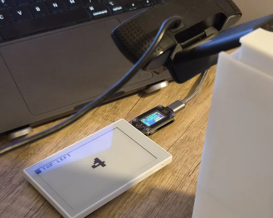
My badge's AGENTS.md, abridged
## The unit

- Know the device's port before opening
  any serial port. Always pass the port.
- mpremote reset doesn't reset this board:
  make reset pulses EN, with esptool.
- mpremote's Ctrl-C stops the programme
  until a reset: leave the unit reset.
Skills that count
A skill is a folder with a SKILL.md and scripts. Read them before installing them.
mpremote: runs code on the board, copies files, keeps one session open.
circuitpython-runner runs code; hw-tests-runner runs tests on the board.
upy-gen-driver writes a driver from a datasheet; upy-slim-driver cuts its RAM.
The rest of the owl
Owlio, by Jonathan Sanderson, Northumbria University, and Tanwen Sanderson, age 7
Together we've covered:
- Device Resources
- Drivers
- Debugging
- Tooling
- AI
Thank you
Questions?